
 United Kingdom
 France
 Germany
 Netherlands
 Sweden
 USA
USA
 Italy
Italy
 Spain
Spain
More From Contributor


Loco Decoder V1.3 NMRA Compliant
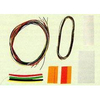
The Hornby locomotive decoders may be used with all standard digital control equipment that conforms to the NMRA standards Control of the motors rotational speed load compensation Acceleration and deceleration separately adjustable Selectable for operation with 14 28 128 speed steps Programming on main track Four OnOff function outputsTwo of the function outputs are dedicated for the head tail lights Operation on standard DC systems analogue operation possible Motor overload current protection With NMRA RP911 NEW652 medium plug Technical Specification Maximum current carrying capacity of the decoder in sum 1A Rated continuous current output in sum 500mA Continuous motor output current 500mA Function output current 100mA each Address CV 1 CV 1718 1127 19999 Speed Steps Selectable 14 28 128
Dimensions 17 x 10 x 35mm List of supported CVs CV Name CV Default Description Primary Address 1 3 Bits 06 contain an address with a value between 1 and 127 Bit seven must have a value of 0 If the value of Configuration Variable 1 is 00000000 then the decoder will go out of NMRA digital mode and convert to the alternate power source as defined by Configuration Variable 12 Acceleration Rate 3 5 Determines the decoders acceleration rateThe formula for the acceleration rate shall be equal to the contents of CV3896 number of speed steps in use Deceleration Rate 4 5 Determines a decoders braking rate Manufacturer Version No 7 13 Manufacturer defined version info Manufacturers ID 8 48 Values assigned by NMRA EMF Feedback Cutout 10 128 Contains a value between 1 and 128 that indicates the speed
step above which the back EMF motor control cuts off Extended Address 1718 The Extended Address is the locomotives address when the decoder is set up for extended addressing indicated by a value of 1 in bit location 5 of CV29 CV17 contains the most significant bits of the two byte address and must have a value between 11000000 and 11100111 inclusive in order for this two byte address to be valid CV 18 contains the least significant bits of the address and may contain any value Configuration Data 1 29 Decoder Configuration byte 1 Bit 0 Locomotive Direction 0 normal 1 reversedThis bit controls the locomotives forward and backward direction in digital mode only Directional sensitive functions such as headlights FL and FR will also be reversed so that they line up with the locomotives new
forward direction Bit 1 FL location 0 bit 4 in Speed and Direction instructions control FL 1 bit 4 in function group one instruction controls FL Bit 2 Power Source Conversion 0 NMRA Digital Only 1 Power Source Conversion Enabled Bit 5 0 one byte addressing 1 two byte addressing also known as extended addressing All the CVs shown can be programmed in Operating Mode Register CV Mode Paged CV Mode and Direct CV Mode All the CVs shown can be interrogated in all service modes The Hornby Decoder supports programming on the Main Some advice on the current draw of the decoder output The current for all the decoder outputs is supplied by an internal rectifier with a maximum current of 1 Amp and the rated continuous current is 500mAThe sum of all currents to the motor and the function outputs should
not exceed 500mA at normal continuous operation and cannot exceed 1 Amp If the motor current exceeds 500mA the decoder will automatically cut off power to the motor Function outputs are not protected Each individual output can only draw up to its limit For example if a motor requires as much as 400mA continuously then the function outputs combined should not exceed 100mA Therefore if the directional headlights require 50mA then the load Function 1 and Function 2 should not exceed 50mA


Product Description
Reviews/Comments
Add New
Vouchers
No voucher codes found.
Do you know a voucher code for this product or supplier? Add it to Insights for others to use.
Do you know a voucher code for this product or supplier? Add it to Insights for others to use.
 Denmark